Vansim (Dongguan)Hardware Products Co., Ltd.


What are the key design considerations for copper skived heat sinks?
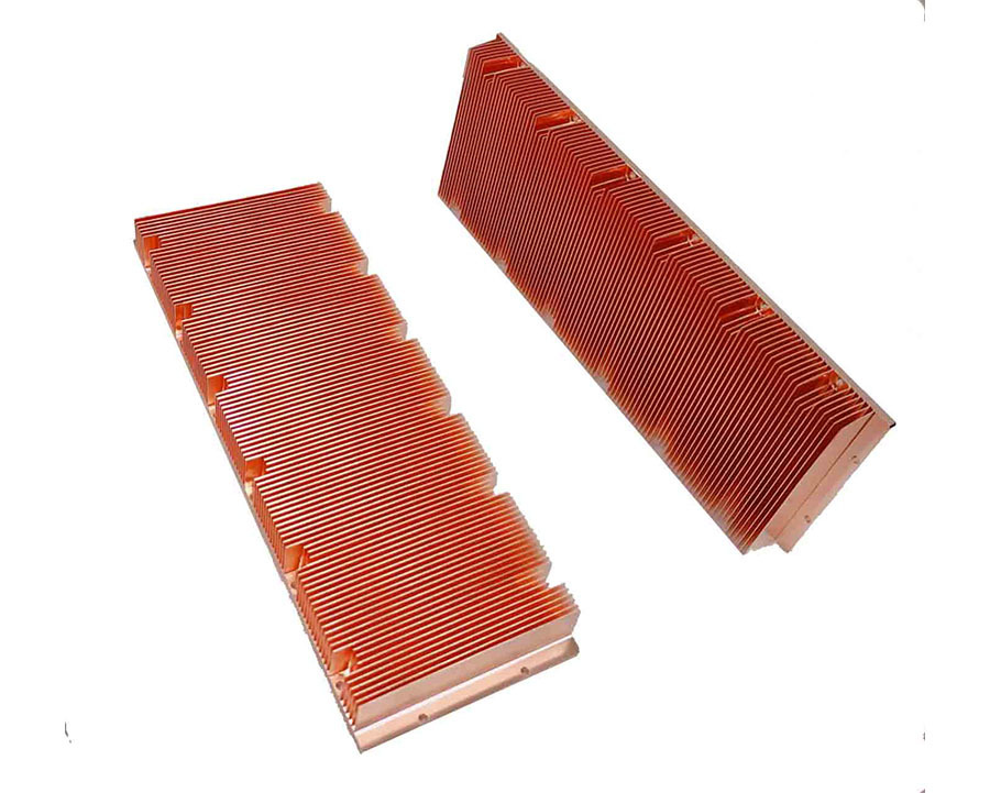
1. Copper skived heat sink Thermal Design Fundamentals
a. Heat Flux and Thermal Conductivity
- Heat Source Characteristics: Understand the power density (W/cm²) of the heat-generating component. Copper’s high thermal conductivity (401 W/m·K) is ideal for high-heat-flux applications (>100 W/cm²), but inefficient interface design (e.g., gaps between the heat sink base and component) can degrade performance. Thermal interface materials (TIMs), such as gap pads or solder, must minimize contact resistance.
- Heat Transfer Path: Optimize the heat flow from the source through the baseplate to the fins. A thick baseplate (e.g., 3–5 mm) reduces thermal spreading resistance, while thin fins (0.2–0.5 mm) maximize surface area for convection.
b. Convection Dynamics
- Forced vs. Passive Cooling:
- Forced Air (fans or blowers): Narrow fin pitches (1–3 mm) and taller fins (50–100 mm) enhance heat transfer by increasing airflow contact. However, tight pitches risk dust accumulation in dirty environments.
- Natural Convection: Wider fin pitches (4–8 mm) and vertical orientation promote buoyancy-driven airflow. Taller fins (80–150 mm) improve natural convection but may compromise mechanical stability.
- Airflow Direction: Align fins with the dominant airflow (e.g., horizontal for desktop PCs, vertical for rack-mounted servers) to minimize stagnant zones.
2. Copper skived heat sink Mechanical and Structural Design
a. Skiving Fin Geometry and Aspect Ratio
- Skiving Fin Thickness: Thinner fins (0.1–0.3 mm) increase surface area but may bend or break during manufacturing or handling. Thicker fins (0.5–1 mm) are more robust for high-vibration environments (e.g., automotive), though they reduce total fin count and heat dissipation.
- Skiving Fin Height and Pitch:
- Aspect Ratio (height/thickness): High-aspect-ratio fins (e.g., 100:1) are achievable via skiving but risk tip deflection. Structural supports (e.g., inter-fin bridges) may be added for stability.
- Pitch Optimization: Balance between fin density and airflow resistance. For example, in 5G RF modules, sub-millimeter pitches (0.8–1.2 mm) maximize surface area for compact active cooling, while industrial heat sinks use wider pitches (3–5 mm) for debris resistance.
b. Skiving fin Baseplate and Material Selection
- Baseplate Thickness: A thicker baseplate (e.g., 4–6 mm) reduces thermal resistance for concentrated heat sources (e.g., CPUs), while a thinner baseplate (1–2 mm) suffices for distributed heat loads.
- Material Alloy: Pure copper (C11000) offers maximum conductivity, but alloys like copper-tungsten (for strength) or copper-nickel (for corrosion resistance) may be preferred for aerospace or marine applications.
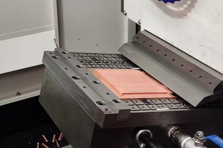
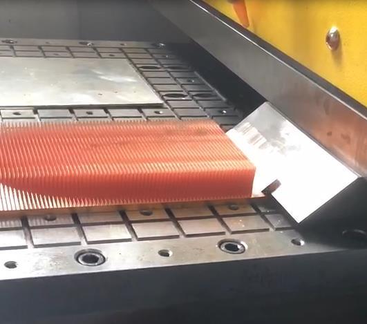
3. Copper skived heat sink Manufacturing Feasibility
a. Skiving Process Constraints
- Tooling Limitations: Skiving uses precision blades to cut fins from a solid copper block. Minimum fin thickness is ~0.1 mm, limited by blade sharpness and material ductility. Tighter tolerances (±0.02 mm) are possible but increase cost.
- Burr Control: Post-skiving deburring (e.g., chemical etching or electropolishing) is critical to avoid sharp edges and ensure smooth fin surfaces, which improve airflow and prevent short circuits in electronics.
b. Surface Treatment and Coating
- Oxide Layer Management: Copper oxidizes over time, increasing thermal contact resistance. Plating (e.g., nickel, gold, or tin) protects against corrosion, enhances solderability, and improves emissivity for radiation heat transfer (e.g., in aerospace).
- Smoothness for Airflow: Polished fins reduce air friction, while rough surfaces (e.g., via bead blasting) can slightly enhance convective heat transfer through turbulence at the cost of higher pressure drop.
4. Copper skived heat sink Environmental and Application-Specific Factors
a. Environmental Demands
- Temperature Range: Copper performs well from cryogenic (-270°C in quantum computing) to moderate high temperatures (~250°C), but prolonged exposure above 300°C can degrade mechanical properties.
- Corrosion Resistance: In humid or saline environments (e.g., coastal infrastructure), nickel or epoxy coatings prevent pitting and green oxide formation.
b. Size and Weight Constraints
- Compact Systems: In laptops or medical devices, prioritize thin fins (0.2–0.4 mm) and low-profile designs (<20 mm height) over pure thermal performance.
- Weight Sensitivity: In aerospace, use lightweight copper alloys or hybrid designs (copper base with aluminum fins) to balance thermal and mass requirements.
 |  |  |
5. Copper skived heat sink Thermal Interface and Integration
a. Attachment Methods
- Bonding Techniques:
- Soldering/Welding: Provides permanent, low-resistance joints but requires precise temperature control to avoid copper oxidation.
- Clamping/Screwing: Allows easy disassembly for maintenance but may introduce mechanical stress or thermal interface gaps.
- Heat Pipe/Vapor Chamber Integration: For ultra-high heat fluxes, embed heat pipes in the baseplate to spread heat across a larger fin array, reducing hotspots.
6. Copper skived heat sink Testing and Validation
- Thermal Simulation: Use computational fluid dynamics (CFD) to model airflow, temperature distribution, and pressure drop. Key metrics include thermal resistance (Rth), heat dissipation capacity (Qmax), and maximum hotspot temperature.
- Physical Testing: Validate designs with thermal imaging, wind tunnel tests, and long-term reliability trials (e.g., thermal cycling to assess fatigue in fins).
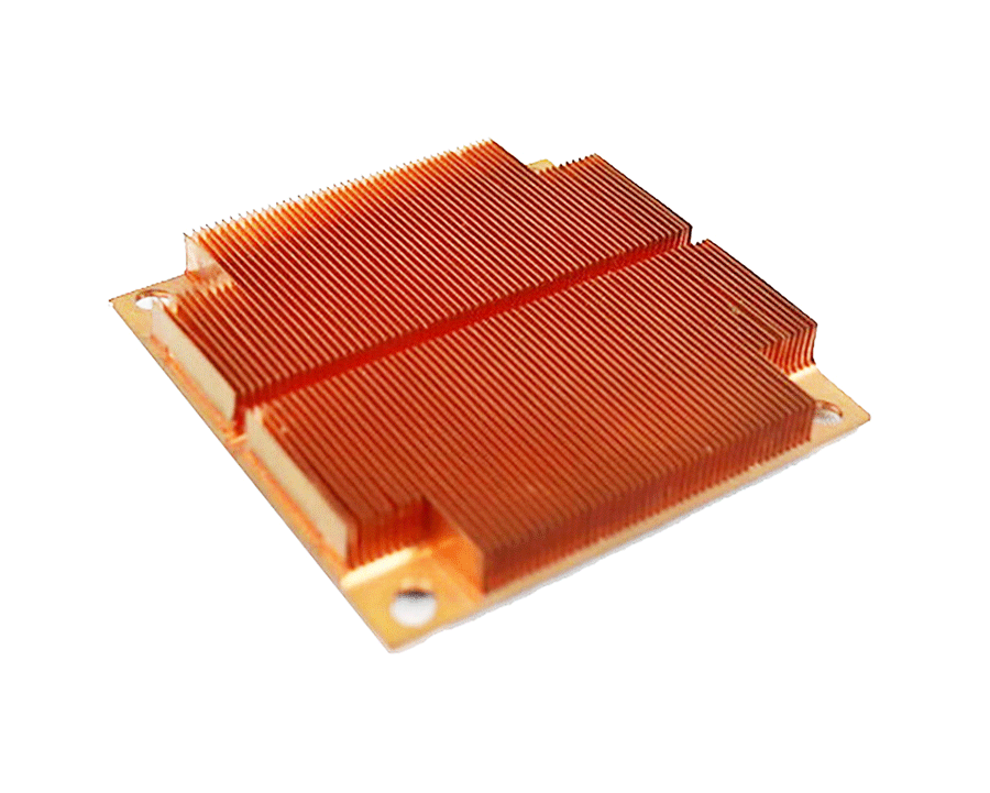
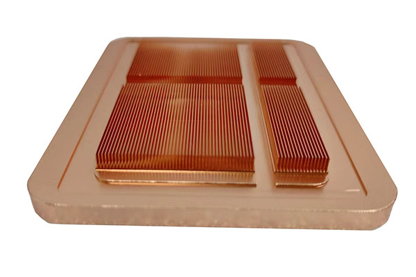
Conclusion
IGBT cooling copper skived heat sink
Contact Us
Classification


// CONTACT US
Didn'T Find The Service You Want?
For inquiries about our products, please email to us and we will be in touch within 24 hours.
We Support Customization
Continue To Create Greater Value For Customers
Contact Us
No. 10, Minying West Road, Hengli Town, Dongguan City, China 523390