Vansim (Dongguan)Hardware Products Co., Ltd.


How does the high power embedded heat pipes skiving fin heat sinks applied for the laser air cooling system?
1. Key Challenges in Laser Air Cooling Systems
- Thermal distortion of optical components (e.g., lenses, gain media), degrading beam quality.
- Reduced efficiency and lifespan of laser diodes and electronic drivers.
- Potential system failure if heat is not rapidly dissipated.
2. Structure of High-Power Embedded Heat Pipe Skiving Fin Heat Sinks
Core Components:
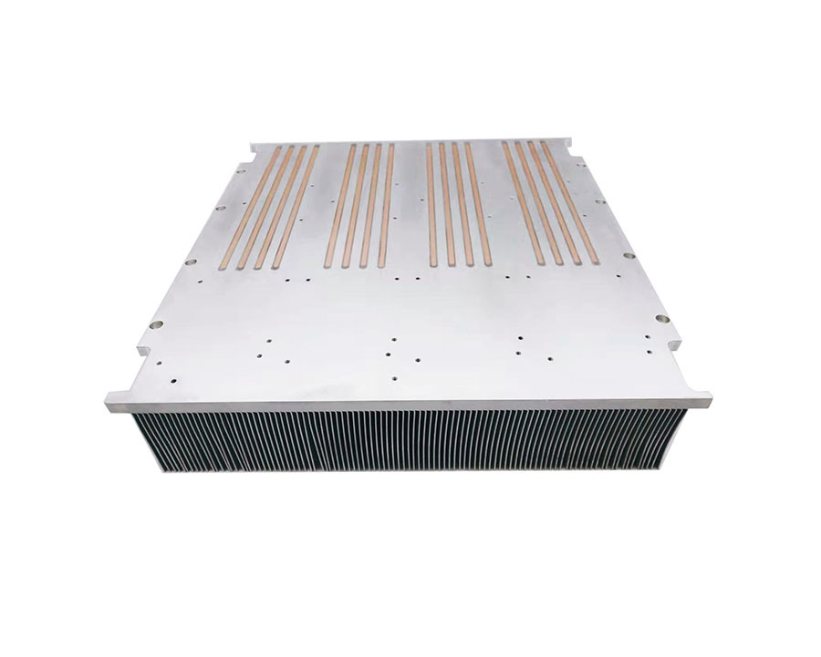
- Base Plate with Embedded Heat Pipes:
- Made of copper or copper-aluminum composite for high thermal conductivity.
- Heat pipes (typically copper with sintered wicks) are embedded within the base to rapidly transport heat away from the laser’s heat-generating components (e.g., diode arrays, pump modules).

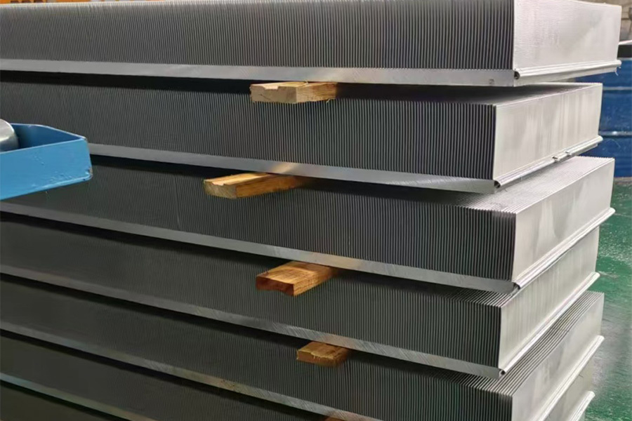
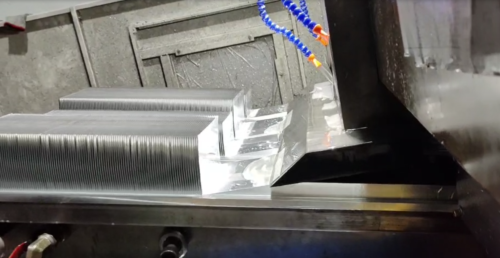
- Skiving Fins heat sink:
- Thin, high-density fins made via skiving process (a machining process that cuts fins from a solid aluminum or copper block), creating a monolithic structure with the base.
- Fins have minimal thermal resistance due to their seamless integration with the base.
- Airflow Optimization:
- Fins are often arranged in parallel rows to align with forced air flow (via fans or blowers), maximizing convective heat transfer.
3. Working Principle in Laser Systems
Step 1: Heat Absorption at the Base
- The base plate is directly attached to the laser’s heat source (e.g., a diode pump module) using thermal interface materials (TIMs, such as gap pads or thermal grease).
- Heat from the laser is conducted into the base and absorbed by the embedded heat pipes.
Step 2: Heat Transport via Heat Pipes
- Inside the heat pipes, a working fluid (e.g., water or acetone) vaporizes at the hot base (evaporation zone).
- Vapor flows rapidly to the cooler fin end of the heat pipe (condensation zone), driven by pressure differences and capillary action in the wick structure.
- This phase change (liquid → vapor → liquid) enables ultra-fast heat transport, overcoming the limitations of pure conduction.
Step 3: Heat Dissipation via Skiving Fins
- At the condensation zone, vapor releases heat to the skiving fins, condensing back into a liquid.
- The skiving fins’ large surface area and high density enhance convective heat transfer to the air stream (forced or natural convection).
- Cooled liquid returns to the base via the wick, completing the cycle.
Step 4: Airflow Integration
- Forced air cooling (e.g., axial or centrifugal fans) is typically used to maintain high airflow velocity across the fins, minimizing thermal resistance and preventing hotspots.
4. Advantages for Laser Air Cooling
(1) Ultra-High Heat Dissipation Capacity
- Heat pipes enable thermal conductivity up to 10,000 W/m·K (far exceeding solid metals), quickly evacuating heat from localized hotspots (e.g., laser diodes).
- Skiving fins provide a high surface-area-to-volume ratio (e.g., 500–1000 fins per meter), increasing heat dissipation by 30–50% compared to traditional extruded fins.
(2) Isothermal Performance
- Heat pipes minimize temperature gradients across the heat sink, ensuring uniform cooling of sensitive laser components (e.g., optical resonators) and preventing thermal stress.
(3) Compact and Robust Design
- Skiving fins are mechanically strong (no delamination risk) and ideal for high-vibration environments (e.g., industrial lasers).
- Embedded heat pipes reduce overall thickness, fitting into tight laser enclosure spaces.
(4) Reliability and Low Maintenance
- No moving parts in heat pipes (long lifespan: 10+ years).
- Air cooling eliminates risks of liquid leaks or corrosion, critical for maintenance-intensive laser systems.
(5) Customization for Laser Geometry
- Heat pipes can be bent or routed around optical components, adapting to complex laser cavity layouts.
- Skiving fins can be tailored for airflow direction (e.g., horizontal or vertical fins to match fan orientation).
5. Typical Applications in Laser Systems
(1) Industrial Laser Machining
- Cooling high-power fiber lasers (2–10 kW) used in cutting, welding, or marking.
- Example: Heat sinks integrated into laser head modules to cool pump diodes and gain fibers.
(2) Aerospace and Defense Lasers
- Air-cooled solid-state lasers for directed energy systems or airborne applications, where weight and reliability are critical.
(3) Medical Lasers
- Cooling compact laser systems (e.g., surgical lasers) in sterile environments, where liquid cooling is impractical.
(4) Research and Laboratory Lasers
- Precise cooling of ultra-fast lasers (e.g., femtosecond lasers) to maintain optical stability.
6. Design Considerations for Laser Systems
(1) Thermal Interface Optimization
- Use high-conductivity TIMs (e.g., silver-filled thermal pads, ≥10 W/m·K) to minimize contact resistance between the laser and heat sink base.
(2) Airflow Dynamics
- Calculate required airflow (CFM) based on heat load:
- For a 5 kW laser, typical airflow might be 200–300 CFM (forced air) to maintain <50°C component temperature.
- Avoid recirculation of hot air using baffles or ducting.
(3) Material Selection
- Base/Heat Pipes: Copper for high conductivity (401 W/m·K); aluminum for lightweight systems (205 W/m·K).
- Fins: Aluminum (cost-effective) or copper (higher conductivity for extreme heat).
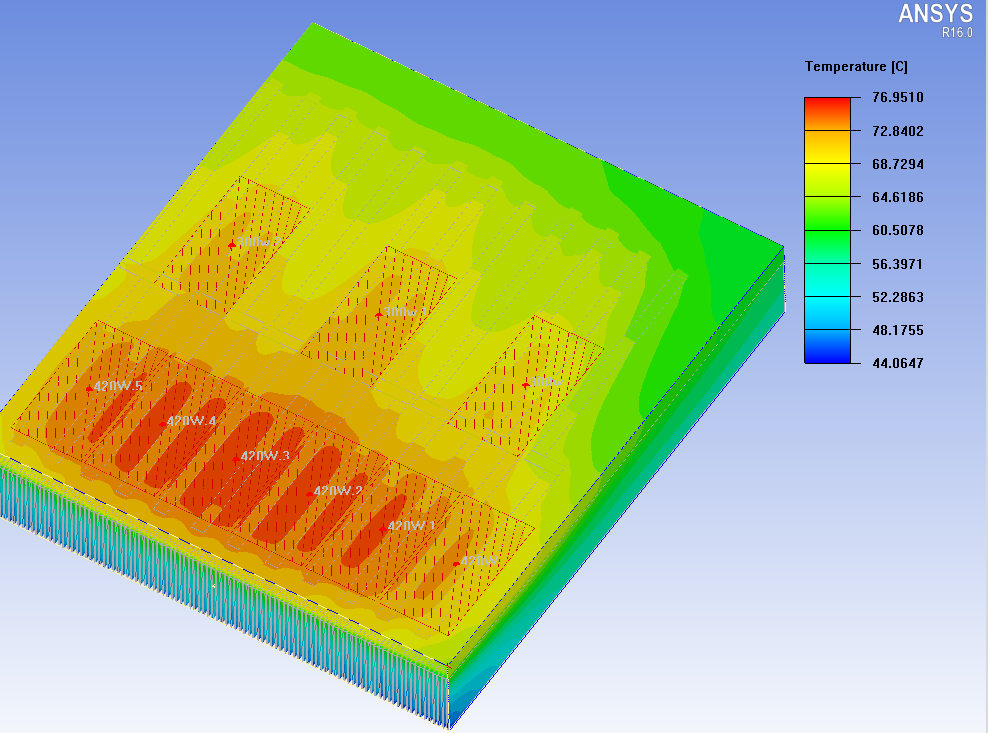
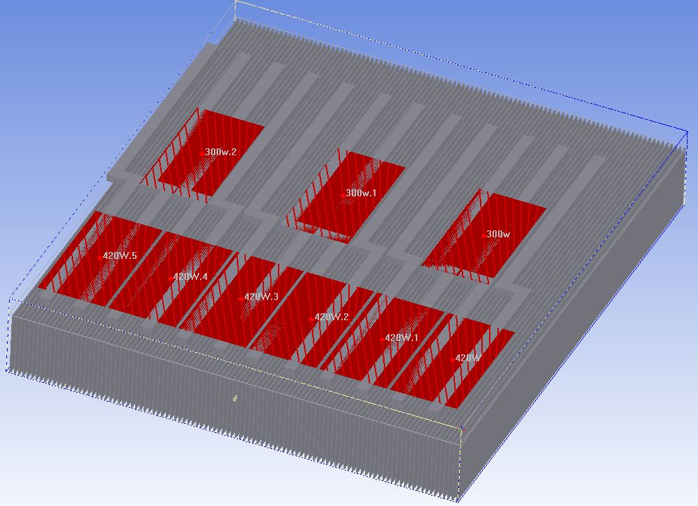
(4) Thermal Simulation
- Use CFD (computational fluid dynamics) to model airflow and temperature distribution, optimizing fin spacing and heat pipe placement.
7. Comparison with Other Cooling Methods
embedded heat pipe skiving fin heat sink for fiber laser air cooling system
Contact Us
Classification


// CONTACT US
Didn'T Find The Service You Want?
For inquiries about our products, please email to us and we will be in touch within 24 hours.
We Support Customization
Continue To Create Greater Value For Customers
Contact Us
No. 10, Minying West Road, Hengli Town, Dongguan City, China 523390