Vansim (Dongguan)Hardware Products Co., Ltd.




What're the important points to manufacturing FSW process optical fiber laser liquid cooling cold plate?

I. Key Points in FSW Process Control for the FSW liquid cold plate
1. Tool Design for FSW
- The FSW tool (pin and shoulder) must be optimized for the material (e.g., aluminum alloys like 6061-T6 or copper). For aluminum, a threaded pin with a convex shoulder promotes better material mixing and reduces voids. For copper (higher thermal conductivity but lower FSW compatibility), a tapered pin with a larger shoulder may be needed to generate sufficient heat for plasticization.
- Regularly inspect the tool for wear (e.g., pin tip erosion), as worn tools can cause insufficient penetration, poor weld fusion, or surface defects (e.g., “onion rings” or voids).
2. Welding Parameters Optimization
- Rotation Speed vs. Traverse Speed:
- Heat Input Balance: Higher rotation speeds increase heat generation (beneficial for materials with high thermal conductivity like copper) but may cause overheating and grain coarsening in aluminum. Lower traverse speeds allow more time for material flow but risk excessive deformation.
- Example for Aluminum: A typical range is rotation speed: 800–1,200 RPM, traverse speed: 50–100 mm/min, with axial force: 5–8 kN. For copper, higher rotation speeds (1,500–2,000 RPM) and lower traverse speeds (20–50 mm/min) may be required to overcome higher yield strength.

Precautions for Optical Fiber Slot Machining
1. Slot Design and Tolerance Control
- Precision Machining Requirements:
- Optical fiber slots must have tight dimensional tolerances (e.g., width: ±0.01 mm, depth: ±0.02 mm) to ensure snug fitment of fibers (typically 125 μm in diameter for single-mode fibers) without damaging the cladding or coating.
- Radius at Slot Edges: Avoid sharp edges (e.g., use a 0.05–0.1 mm radius) to prevent stress concentrations that could fracture fibers during assembly.
- Thermal Clearance:
- Ensure slots are positioned away from high-heat zones (e.g., laser diode mounting areas) or incorporate thermal barriers (e.g., insulating layers) to prevent heat transfer to fibers, which can degrade optical performance.
 |  |
2. Machining Methods and Tooling
- Micro-Machining Techniques:
- Use high-precision CNC milling with micro-end mills (diameter: 0.1–0.5 mm) or ultrasonic machining for slots in hard materials like copper. For aluminum, diamond-coated tools reduce burrs and improve surface finish.
- Avoid Material Smearing:
- In copper, slow cutting speeds (e.g., 5–10 m/min) and high feed rates (e.g., 0.01–0.03 mm/rev) prevent smearing of soft material into the slot, which could trap fibers or cause uneven seating.
- Deburring and Surface Finish:
- Post-machining, use electrochemical machining (ECM) or plasma etching to remove burrs and achieve a surface roughness (Ra < 1.6 μm) that prevents fiber abrasion.
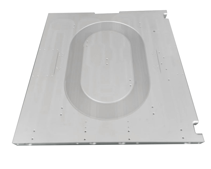
optical fiber laser liquid cold plate
Contact Us
Classification

// CONTACT US
Didn'T Find The Service You Want?
For inquiries about our products, please email to us and we will be in touch within 24 hours.
We Support Customization
Continue To Create Greater Value For Customers
Contact Us
No. 10, Minying West Road, Hengli Town, Dongguan City, China 523390