Vansim (Dongguan)Hardware Products Co., Ltd.




Costa-Rica high power IGBT cooling embedded heat pipe heat sink
Category:
Costa-RicaHeat Pipe Heat Sinks
Product Description
How does the embedded heat pipe heat sink worked for high power IGBT cooling ?
1. Key Challenges in High-Power IGBT Cooling
- Junction Temperature Limitations: IGBTs have a maximum junction temperature (typically 150–200°C), beyond which reliability degrades rapidly.
- Non-Uniform Heat Distribution: Hotspots form near the die attach points or bonding wires, leading to thermal stress and potential failure.
- Size and Weight Constraints: Compact designs are required for applications like electric vehicles (EVs) or aerospace systems.
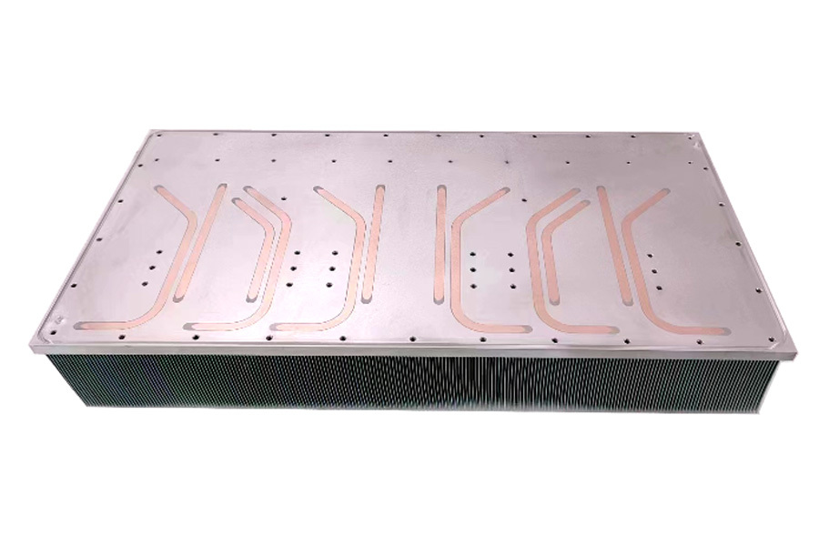
2. Structure of Embedded Heat Pipe Heat Sinks for IGBTs
Core Components:
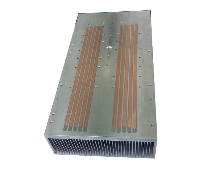
- Base Plate with Embedded Heat Pipes:
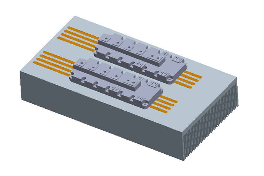
- The base (usually copper or copper-aluminum composite) is directly attached to the IGBT module’s underside.
- Heat pipes (copper with wicks) are embedded within the base, running perpendicular to the heat flow direction to quickly carry heat away from the IGBT’s hotspots.
- Heat Dissipation Section:
- Fins or Cold Plates: Extruded/aluminum fins, skived fins, or flat plates (for forced air or liquid cooling) are integrated with the heat pipes’ condenser section.
- In forced air systems, fins are densely packed (e.g., 2–5 mm spacing) to maximize convective cooling. In liquid-cooled systems, the heat pipes may terminate in a cold plate with microchannels.
- Thermal Interface Materials (TIMs):
- Gap pads, thermal grease, or phase-change materials (PCMs) with high conductivity (≥5 W/m·K) ensure efficient heat transfer from the IGBT to the base plate.
3. Working Principle for IGBT Cooling
Step 1: Heat Absorption at the Base
- The IGBT module’s heat (generated primarily in the silicon die) is conducted through the module’s ceramic substrate (e.g., AlN, Al₂O₃) and metal baseplate to the heat sink’s base.
- The embedded heat pipes absorb this heat at their evaporation zone (in direct contact with the IGBT’s hotspots).
Step 2: Heat Transport via Heat Pipes
- Inside the heat pipe, a working fluid (e.g., water, methanol) vaporizes at the hot base, absorbing latent heat.
- The vapor flows rapidly (at near-sonic speeds in high-power pipes) to the condensation zone (cooler fin/cold plate section), driven by pressure gradients and capillary action in the wick.
- This phase change enables heat transport with minimal temperature drop, even over long distances (e.g., 10–30 cm), overcoming the limitations of solid conduction.
Step 3: Heat Dissipation
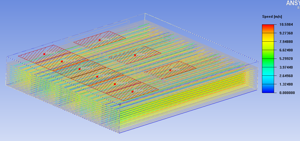
- In forced air cooling:
- The vapor condenses on the fins, releasing heat to the airflow (generated by fans or blowers). The fins’ high surface area (e.g., 1000–2000 cm² per heat sink) enhances convective heat transfer.
- Cooled liquid flows back to the base via the wick, completing the cycle.
- In liquid cooling (e.g., cold plate integration):
- The heat pipe’s condenser is bonded to a cold plate with internal channels for coolant (e.g., water-glycol). Heat is transferred to the liquid, which is then routed to a radiator.
Step 4: Thermal Management Integration
- Temperature sensors monitor the IGBT junction or heat sink surface, adjusting fan speed or coolant flow to maintain optimal temperatures.
// CONTACT US
Didn'T Find The Service You Want?
For inquiries about our products, please email to us and we will be in touch within 24 hours.
We Support Customization
Continue To Create Greater Value For Customers
Contact Us
No. 10, Minying West Road, Hengli Town, Dongguan City, China 523390